

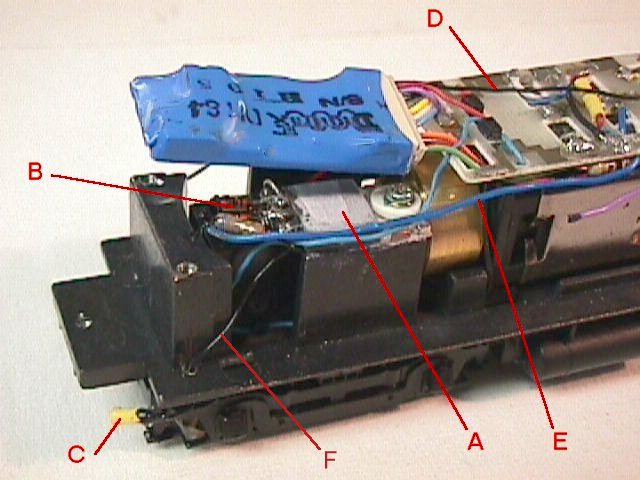
Mount the TIP 31 (Fig. 7-A) on your locomotive frame with heat sink
grease and insulating spacers. Check for any shorts to your frame prior
to powering up the unit. It will dissipate about 2 watts when the couplers
are open. I filed away the epoxy encapsulation on the power transistor
until it was almost even with the leads to make it thin enough to fit into
the space I had. The advantages of this circuit over a straight resistor
are several. First, it is not sensitive to variations in DCC booster voltage,
second it is more easily fitted into a tight space, third it can be bolted
in place for good heat transfer, and fourth, it allows several actuators
to be used in series without any changes in values. I mounted all the other
components on the leads of the power transistor. (Fig. 7-B) Here wecan
see the blue common lead from the decoder (Fig. 7-E) and the current limited
lead passing to the first actuator. (Fig. 7-F) One of the connectors (Fig.
7-C) also shows clearly. The wire that connects between the two actuators
is visible at Fig. 7-D.