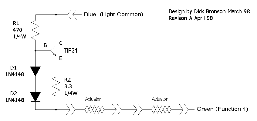
Fig. 8a NPN two diode Muscle Wire current limiter circuit.

Fig. 8a NPN two diode Muscle Wire current limiter circuit.
Lets do the math to figure out the resistor values. First lets do R2. The textbook formula for voltage current and resistance is E=IR. "E" is Electromotive force. (voltage) "I" is for current (apparently "C" had already been spoken for by capacitance) and "R" is resistance. The forward voltage drop for a silicon diode or a common silicon transistor is pretty close to six tenths of a volt. To figure out the voltage across R2 we add the voltages of the two diodes, then subtract the voltage of one transistor junction. That is .6 plus .6 minus .6 which leaves us with .6. We also know that we want 180 ma. of currrent to flow. to find out the resistance we can re-arrange the formula to be E/I=R which is .6/.18 = 3.3333.... The closest standard value is 3.3 ohms.
Next lets tackle R1. The gain (amount of amplification) in the transistor is only guarenteed to be 10 or more. That means that we need to have at least 1/10 of our load current or 18 ma going through R1 and to the transistor base. Again we know "E" and "I" and need to discover "R". Working on the "N" setting of DCC we can still expect about 10V. After removing the 1.2 volts of the two diodes we have 8.8 volts remaining. That gives us 8.8/.018=488, the closest standard value is 470 ohms. To figure the power in R2 the formula is I*E=W or .6 * .18 = .108W (about 1/10W) For R1 the formula is E*E/R=W or 10*10/470=.213 or just a little under 1/4W. We could use a smaller wattage resistor for R2, but R1 needs to be at least 1/4W.
While we are crunching numbers lets go ahead and do the transistor power. For it lets assume an HO setting which will give us about 12V. Again our formula is I*E=W which is .180*12=2.16W