

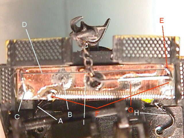
Power from the current limiter feeds into the actuator at the slip-on connector (Fig 6-H) made from a machined IC socket removed from it's plastic moulding. This socket is insulated with a bit of shrink tubing and slips onto a piece of wire soldered to the bottom (engine side) of the actuator board at Fig 6-G. From there power flows both to the pivot and the spring anchor point. (Fig 6-F) From these two points power travels through the "T" bar itself to one end of the muscle wire. (Fig 6-E) From there it flows through the wire, (Fig 6-D) heating it to over 70 degrees C in the process. The current continues via the fixed anchor point (Fig 6-C) to the second slip on connector (Fig 6-B) and then via a jumper wire (Fig 6-A) to the other end of the engine. After passing through the second actuator it connects to the DCC function control power lead.