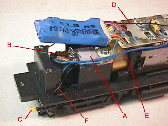
Figure 7 Photo by Bill Summers
Power from the current limiter (Fig 7-F) feeds into the actuator at
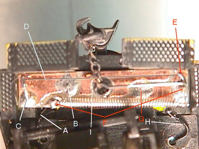
the slip-on connector (Fig 6-H) made from machined IC sockets. This socket
is insulated with a bit of shrink tubing (Fig 7-C) and slips onto a piece
of wire soldered to the bottom (engine side) of the actuator board at Fig
6-G. From there power flows both to the pivot and the spring anchor point.
(Fig 6-F) From these two points power travels through the "T" bar itself
to one end of the muscle wire. (Fig 6-E) From there it flows through the
wire, (Fig 6-D) heating it to over 70 degrees C. The circuit continues
via the fixed anchor point (Fig 6-C) to the second slip on connector (Fig
6-B) and then via a jumper wire (Fig 6-A) (Fig 7-D) to the other end of
the engine. After passing through the second actuator it connects to the
DCC function control power lead.
Figure 7
Photo by Bill Summers
Mount the TIP 31 (Fig 7-A) on your locomotive frame with heat sink grease and insulating spacers. Check for any shorts to your frame prior to powering up the unit. It will dissipate about 2 watts when the couplers are open. I filed away the epoxy encapsulation on the power transistor until it was almost even with the leads to make it thin enough to fit into the space I had. The advantages of this circuit over a straight resistor are several. First, it is not sensitive to variations in DCC booster voltage, second it is more easily fitted into a tight space, third it can be bolted in place for good heat transfer, and fourth, it allows several actuators to be used in series without any changes in values. I mounted all the other components on the leads of the power transistor. (Fig 7-B)
You will need to limit the current to not over 200ma. unless you like fried decoder. This (or any other) current limiter will dissipate about 2W, so mount it on the frame someplace away from the plastic body shell. It can be either a resistor (about 40 ohms 2W) or a transistorized current source.
Fig. 8 Muscle Wire current limiter circuit.
Obviously you may use some other power transistor that you have around
the bench. If you use a PNP unit, just reverse the diode directions and
the blue and green decoder leads. Finding a 3.3 ohm resistor is not easy.
You can put 3 10ohm units in parallel. You may also use 3 diodes instead
of 2 in series, and use a 6.8ohm resistor. (I know, big help. <g>) Those
with very sharp eyes may notice that the photo (Fig. 7) is actually of
a limiter made with a PNP transistor, 6.8 ohm resistor, and 3 diodes.