In order to provide an easy way to
connect Block Occupancy Detectors and/or turnout position feedback contacts
to either a PIA-8255, DS-54, or other signal controller boards this board
provides the necessary pull-up resistors. It also acts as a convenient
gathering point for these input devices. Output is via a standard 10 conductor
flat ribbon cable. Power for the pull-up resistors is normally provided
from the controller device. If desired, optional traces are provided allow
you to supply the pull-up voltages directly.
TSB Parts layout
The Resistor pack may be mounted in either direction, as power is provided to each end. The 10 pin header alignment key faces the resistor pack. Normally two 8 position screw terminal strips will be used. (unless you use the optional pull-up power connections) To mount the board to your layout benchwork use two #4 screws. To space the board out from the benchwork use a couple of #6 hex nuts as spacers.
Cable Pin-outs
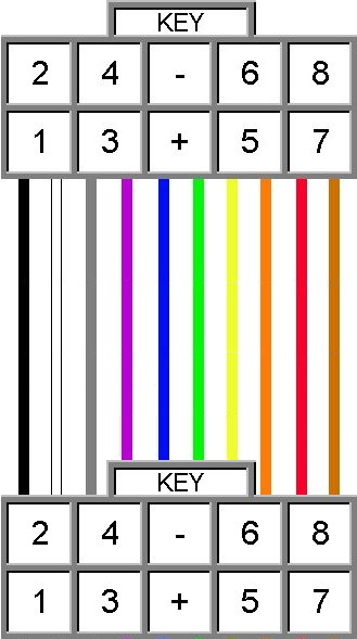
Pin-out for CAB-10x--

Pin-out for DX-54 External Input Connector
The Brown lead (ground connection)
connects to the DS-54 Negative Common screw terminal. The white lead connects
to any one of the "Green" wires on the DS-54 outputs. The remaining eight
leads are connected to the 9 pin External Input Connector.
|
|
|
|
|
|
|
|
|
|
|
|
|
|