Capacitors:
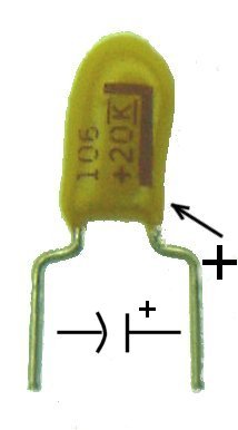
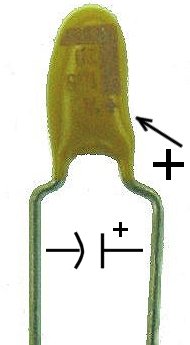
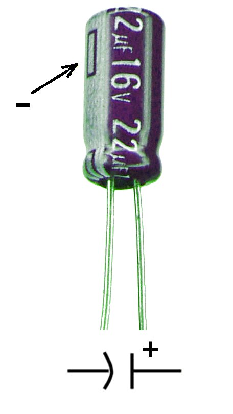
Aluminum Electrolytic and Tantalum capacitors are polarity sensitive.
They can be damaged by inserting them in reverse in power circuits. If
they are reversed in a timing circuit it will probably prevent proper operation.
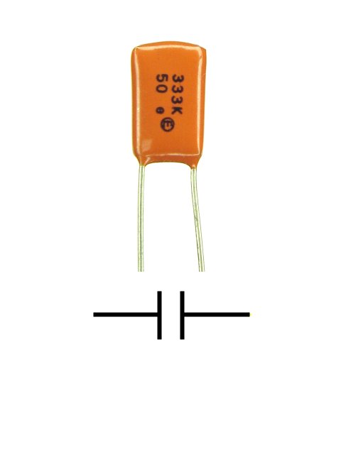
Ceramic and Mylar capacitors on the other hand may be installed in either
direction. Capacitors may be value marked in several ways. The most common
methods are either the actual value in Mfd. (E.g. 22µF which is 22
Mfd or 1µ5 which is 1.5 Mfd) or by the value in picofarads (millionths
of a Mfd) indicated numerically by the first two digits of the value followed
by the number of zeros. (E.g. 106 which is 10 followed by 6 zeros or 10,000,000
Pf or 10 Mfd.) Usually the voltage rating is given in volts and may or
may not be followed by a "v". Some tantalum capacitors are color coded
using the resistor color codes and the numbering system. (band, top, side
stripe or dot)
1. 10 Mfd Tantalum 20V (marked 106 or 10,000,000 Pf)

2. 1.5Mfd Tantalum 20V (marked 1µ5 or 1.5 Mfd)
3. 22 Mfd Aluminum Electrolytic 16V (marked 22µF or 22 Mfd)
4. .033 Mfd Mylar 50V (333 or 33,000 Pf)
5. 0.1 Mfd Monolithic Ceramic 5V (marked 104 or 100,000 Pf)
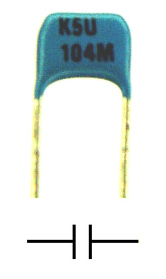
6. Another very small 0.1 Mfd Monolithic Ceramic of unknown voltage
(also marked 104 or 100,000 Pf)
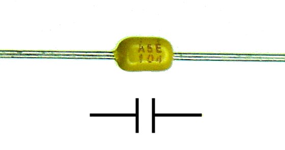
Items 5 and 6 are used as bypass capacitors on boards with digital logic circuits. Many types of logic chips draw much more power during the time they are changing state than they do normally. These caps provide the needed surge current and prevent these power pulses from disturbing other nearby chips. They are located as near as possible to each chip. Large boards may have dozens of these capacitors distributed around the power circuits to prevent false triggering and the resulting errors.