
As in most of the other RR-CirKits products, low cost dictated the use
of readily available inexpensive parts, but not necessarily the fewest
parts. Inputs were designed to be connected in parallel with the ACL-7122
Computer I/O so as to allow the use of a mixed system. (Much like the prototype
where a local controller actually drives the signals.)
SLB Parts Reference
Each Signal Controller board can control up to 8 signal heads. This number was chosen to fit in with the common use of ten wire ribbon cables to interconnect items. This requires the use of two lamp driver boards per signal controller. By having the lamp drivers on separate boards, then any type of signal such as LED's or incadecent lamps may be easily accomadated.
No matter what method of signaling is chosen for your railroad, you will still need many wires to actually accomplish the job. Wires must go to each signal head from their controllers. Wires must also go from each detector to their controllers. Wires must pass information from one block to the next. Wires are needed to feed switch point position information to the controllers. I have chosen to use flat ribbon cable and IDC connectors as much as is possible to keep all of this wiring as neat and easy as possible. The only exceptions to this on the SLB are the power leads, and optionally some direct connections needed to properly control the approach aspects at passing sidings and junctions.
To operate signals in anything but the most simplistic manner requires logic of some sort or other. This logic can take the form of statements in a computer program, interconnections between relays, or wire jumpers on a board. The SLB uses wire jumpers and shorting blocks to "program" the logic for each signal. Taken one signal at a time this logic is not very difficult to understand nor to "program". Only as the system grows does it seem to become more complex. Therefore it is very important that you keep good records for each signal. Even with just the 8 signal logic elements on each SLB it can quickly become confusing if you do not document and plan ahead.
Each signal control element has several inputs and outputs. The primary inputs are the three that each can force a "Stop" aspect. They are "TC" (Track Circuit), "SI" (Switch Interlock), and CTC (Centralized Traffic Control). The other two inputs are Approach Enable and Lighting Enable. The Approach Enable input causes an "Approach" aspect if the controller is not already in the "Stop" aspect. The Lighting Enable is used if the signal is to be approach lighted, and enables the "Clear" aspect if there is no more restrictive aspect in effect. For constant lighted signals the Lighting Enable pins are all jumpered to ground.
There are 4 outputs. The Enable Lighting output feeds forward to the next signal control element to allow it to use the approach lighted mode. In this case the Lighting Enable and Enable Lighting pins are jumpered together between each pair of signals. The second output is fed back to the preceeding signal control element and is the Enable Approach signal. This signal is jumpered to the appropriate Approach Enable input to control the Approach aspect based on the state of the next signal along the selected route. This route selection may be obvious, or at junctions and passing sidings it must be chosen by the switch point position. The remaining two outputs go to the Signal Lamp Drivers. Each pair of signal control lines can set it's signal to one of four states. Typically these will be stop, approach, clear, and dark.
Complete
Passing Siding Wiring Diagram
Complete
Double Track Wiring Diagram
Complete
Single Track Wiring Diagram
 |
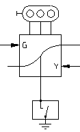
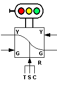
To indicate the signal logic I have borrowed from Wayne Roderick and his early work on signaling. Back in 1969 he created a simple logic representation for a signal controller that with a little bit of modification still works for us today. The "G" input is the approach lighting control. When it is grounded the signal lights green, if there is not a more restrictive aspect called for.Alternatively, the "G" output may be used to activate the following signal's approach lighting control input. In that case the signals will only light in front of a train. The "Y" input activates the approach (or slow) indication if a more restrictive aspect is not called for. The "Y" output is passed back to the preceeding signal to activate it's approach aspect. Both the "G" and "Y" outputs are actually the "R" or stop input, which of course also activates the stop aspect for this signal. I only show two lines to the signal image because the logic output of the RR-CirKits signal controller only uses two lines to the lamp driver board for each signal. In a minute you will also see why I flipped the graphic over. |  |
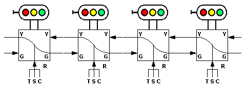
| One of the beauties of this little graphic is that you can string them along one after another very neatly and easily. The "T" "S" "C" red inputs are the Track, Switch, and CTC stop inputs. Three different inputs are provided in order to allow the various stop inputs from different blocks to be tied together without worrying about sneak paths or requiring any extra diodes for isolation. For example, in single track territory the same occupancy detector controls two different signals, one facing in each direction. However the CTC control for these same signals will be different. |  |

As seen in this next image, Jumpers 5 and 6 are actually wired differently from the others. They are a mirror image.
This is done so that you can either jumper the center two columns of pins and have the logic continue
without a break in a single track single direction mode, or else you may jumper the two outer pairs of
columns which will connect signal #4 and Signal #5 input and output lines
to the previous and next SLB's via the link cables. This would be for single track dual direction or double track mode. This
may be confusing, but it can save some wire wrap time so I chose to do it that way.

Once we are past JP-6, then the regular pattern resumes until JP-10 which actually
connects via the link B cable to the next SLB. Remember, you may break the links at any
point as needed to configure a special condition such as a passing track. This just means that
you will need to add wire wrap jumpers to the next signal in logical line rather than placing
simple jumpers from one to the next.

To be continued.