The current crop of accessory decoders are not really a very good solution for driving signals unless one wants to invest in LOTS of decoders. A simple 3 aspect signal takes half of a DS-54 or AD-4 to drive, and then only if you apply a decoder to the outputs. Just driving the signal lamps directly will eat up 3/4 of an entire decoder. What I wanted was a way to take bare computer I/O output and drive signals. The resulting board can also be driven by an accessory decoder if desired. (it will take two accessory decoders to drive one 4 signal decoder board.) By comparison, one computer I/O board can drive as many as 18 decoder boards or 72 signals. (normally it will connect to a mix of detectors and drivers) The newly announced WinLok PIA-8255 driver allows any railroader to take advantage of a computer to control signals of any complexity. This capability is no longer restricted to DCC users of a few manufacturers, but extends to DC users as well.
As in my block occupancy detector, low cost dictated the use of readily available inexpensive parts, not necessarily the fewest parts. A bi-directional output op-amp such as the LM-324 is low cost, and will easily supply enough power to run LED signal lamps directly. The input power requirements for the op-amps are very flexible, and this circuit runs happily with from about a 5VDC to a 25VDC supply. If you build it with the 4 aspect option, then it needs to be powered with at least 10VDC. If your power requirements exceed 15ma per lamp or motor, then you will need to add in the optional driver transistors, which will boost the output up to 100-150ma. continuous, or 500ma. momentary.
This board is primarily designed to be driven directly by either the 8255 parallel I/O in a computer or some type of block circuit controller. It may also be driven with the outputs of an accessory decoder as mentioned above. Each board will drive either four 3, or 4 aspect signals, eight 2 aspect signals, or eight switch motors. It has no local switch machine control capability. That is planned for another board. The DDB is not designed to drive solenoid operated switch machines, but by using the WinLok pulse output option on the PIA-8255 driver and connecting external switching power darlingtons wired to the output connections it could be done. Another option would be to use a capacitor and steering diodes to in effect provide a CD supply to each switch machine.
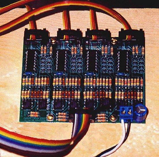
Link to a DDB image (135KB) This picture shows a DDB-G mounted on a layout stringer. The wide flat cable is from the PIA-8255 board, and the 4 narrow flat cables go out to the 4 track side signals controlled by this driver board. The black and white wires are 10VDC power from the layout accessory power bus. (actually +5 and -5 from two old computer power supplies on the LM&PH)
Total 21.01
17.65 Without Q1-Q8
* Starred items optional with some configurations.
Resistors R21-R24 are used to set the brightness of your LED's when using direct drive from the LM324. For LED signals this is normally sufficient. Your values will depend on the LED's you choose for your signals and the operating voltage you choose, and should be adjusted accordingly. The output voltage is approximately 2 volts less than your supply voltage. Another option is to assemble the board without these resistors, then try different values until you are happy with the results. Do not choose a value that will cause more than a 15 ma. load. If you require more than 15 ma. to drive your loads, then you must install the optional driver transistors and use external resistors. The values shown are the ones I use. I operate the boards with 10VDC.
You can direct drive incadecent lamps or low current stall motor switch
machines if the current does not exceed 15 ma. by using the direct outputs
from the LM324. (P2-2,4 and P2-8,10) This drawing shows the 8 output two
aspect option with LED current limiters installed. I have used a lower
resistance for the green LED current limiter to try and compensate for
the reduced sensitivity of the eye to green light, or the lower output
of green LED's or whatever it is that makes the green LED's appear to be
dimmer than the red and yellow ones with the same drive current.
Image
of direct drive parts layout.(29Kb)
For larger current requirements, install the optional driver transistors
and use the second output set. (P2-1,3 and P2-7,9) This image shows the
parts for driving 8 limit switch equipped switch motors. (higher current
than stall motor drives)
Image
of "H" bridge parts layout.(29Kb)
The following image shows the parts layout for the 4 aspect option,
using direct drive LED signals.
Image of
4 aspect parts layout.(30Kb) Omit D1 and R23 for
the 3 aspect option.
Note: Be careful to note the difference between R4-R7 (4.7K) and the other resistors in the same row. (47K) These colors are very difficult to distinguish under some lights.
I purchased all my parts from Jameco http://www.jameco.com