Figure 4
Figure 4
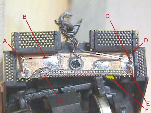
At the right side about 1/16" in from the end and centered vertically is a pivot point. (Fig. 4-C) It is a wire soldered into the PC board and sticking straight up from the board. At the left side is an anchor point. (Fig 4-A) It is a wire soldered into a hole at the lower left corner of the PC board and bent over parallel to the board surface and sticking forward (up) towards the end of the engine. It may be bent from side to side to adjust the tension on the Muscle Wire. About 1/8"-1/4" closer to the center of the loco, but also on the lower left side is a second anchor point. This is for the return spring, and just sticks up like the pivot does, but shorter. (Fig. 4-G)
"Muscle wire" (100 micron) (Fig 4-B) from Jameco at http://www.jameco.com/ is connected from the upper (loco coupler end) side of the "T" arm (Fig 4-D) across the width of the loco to the left fixed anchor. (Fig 4-A) Wind a spring from .009 guitar string (Fig 5-C) and connect it from the lower side of the "T" arm (Fig 4-E) to the spring anchor. (Fig 4-G) Wind the .009 wire close spaced around a 1/16" drill bit shank. I chucked the drill in reverse in my pin vise with the drill flutes just visable. Stick the end of the wire into a flute to hold it and commence winding till you have about 3/4" of spring. You want about 50 grams of tension when you are done. Cutting the spring length such that it is stretched out about 20% when it is installed should come close enough. Clip the wire, and form the ends as shown above. (Form one loop up, and the other down.) A small blob of solder (Fig 5-D) near the loop keeps the "T" bar positioned correctly on the pivot.